![]()
![]()
![]()
![]()
![]()
![]()
Syntax: RCTIME Pin, State, Variable
Measure time while Pin remains in State; usually to measure the charge/discharge time of resistor/capacitor (RC) circuit..
Note: See POT for the BS1.
| BS2, BS2e, and BS2pe | BS2sx | BS2p | BS2px | |
| Units in Variable | 2 µs | 0.8 µs | 0.75 µs | 0.75 µs |
| Maximum pulse width | 131.07 ms | 52.428 ms | 49.151 ms | 49.151 ms |
RCTIME can be used to measure the charge or discharge time of a resistor/capacitor circuit. This allows you to measure resistance or capacitance; use R or C sensors such as thermistors or capacitive humidity sensors or respond to user input through a potentiometer. In a broader sense, RCTIME can also serve as a fast, precise stopwatch for events of very short duration.
When RCTIME executes, it starts a counter (who's unit of time is shown above). It stops this counter as soon as the specified pin is no longer in State (0 or 1). If pin is not in State when the instruction executes, RCTIME will return 1 in Variable, since the instruction requires one timing cycle to discover this fact. If pin remains in State longer than 65535 timing cycles RCTIME returns 0.
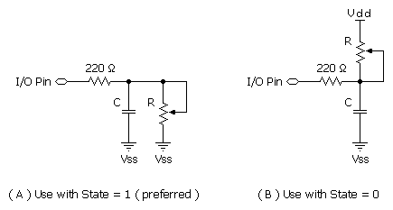
The figure below shows suitable RC circuits for use with RCTIME. Circuits A are preferred, because the BASIC Stamp's logic threshold is approximately 1.4 volts. This means that the voltage seen by the pin will start at 5V then fall to 1.4V (a span of 3.6V) before RCTIME stops. With Circuit B, the voltage will start at 0V and rise to 1.4V (spanning only 1.4V) before RCTIME stops. For the same combination of R and C, Circuits A will yield a higher count, and therefore more resolution than Circuit B.

Before RCTIME executes, the capacitor must be put into the state specified in the RCTIME instruction. For example, with Circuit A, the capacitor must be charged until the top plate at 5V.
Here's a typical sequence of instructions for Circuit A (assuming I/O pin 7 is used):
result  VAR     Word

Test:
  HIGH 7                                ' charge the cap
  PAUSE 1                               '   for 1 ms
  RCTIME 7, 1, result                   ' measure RC discharge time
  DEBUG DEC ? result                    ' display result
  END
Using RCTIME is very straightforward, except for one detail: For a given R and C, what value will RCTIME return? It's easy to figure, based on a value called the RC time constant, or tau (τ) for short. Tau represents the time required for a given RC combination to charge or discharge by 63 percent of the total change in voltage that they will undergo. More importantly, the value t is used in the generalized RC timing calculation. Tau's formula is just R multiplied by C:
τ = R x C
The general RC timing formula uses τ to tell us the time required for an RC circuit to change from one voltage to another:
time = -τ x ( ln(Vfinal / Vinitial) )
In this formula ln is the natural logarithm; it's a key on most scientific calculators. Let's do some math. Assume we're interested in a 10 kΩ resistor and 0.1 µF capacitor. Calculate τ:
τ = (10 x 103) x (0.1 x 10-6) = 1 x 10⁻³
The RC time constant is 1 x 10⁻³ or 1 millisecond. Now calculate the time required for this RC circuit to go from 5V to 1.4V (as in Circuit A):
Time = -1 x 10⁻³ x ( ln(1.4v ÷ 5.0v) ) = 1.273 x 10⁻³
On the BS2, the unit of time is 2 µs, that time (1.273 x 10⁻³) works out to about 635 units. With a 10 kΩ resistor and 0.1 µF capacitor, RCTIME would return a value of approximately 635. Since Vinitialand Vfinal doesn't change, we can use a simplified rule of thumb to estimate RCTIME results for Circuit A:
RCTIME units = 635 x R (in kΩ) x C (in µF)
Another handy rule of thumb can help you calculate how long to charge/discharge the capacitor before RCTIME. In the example above that's the purpose of the HIGH and PAUSE commands. A given RC charges or discharges 98 percent of the way in five time constants (5 x R x C). In Circuits A and B, the charge/discharge current passes through the 220 Ω series resistor and the capacitor. So if the capacitor were 0.1 µF, the minimum charge/discharge time should be:
Charge time = 5 x 220 x (0.1 x 10-6) = 110 x 10-6
So it takes only 110 µs for the capacitor to charge/discharge, meaning that the one millisecond charge/discharge time of the example is plenty.
A final note about the circuits above: You may be wondering why the 220 Ω resistor is necessary at all. Consider what would happen if resistor R was a potentiometer, and were adjusted to 0 Ω. When the I/O pin went high to discharge the capacitor, it would see a short direct to ground. The 220 Ω series resistor would limit the short circuit current to 5V ÷ 220 Ω = 23 mA and protect the BASIC Stamp from damage. (Actual current would be quite a bit less due to internal resistance of the pin's output driver, but you get the idea.)
BASIC Stamp Help Version 2.5.4
Copyright © Parallax Inc.
8/8/2012