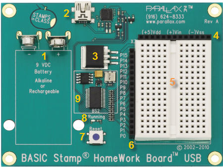

HomeWork Board - USB
- Take a look at your board to get familiar with its parts.

- 9V Battery Clip
 : You can use alkaline or rechargeable 9-volt batteries. Disconnect the battery to turn off power to your board.
- USB Programming Connector
 : This is a USB Mini B socket and USB to serial (RS-232) circuitry for programming and for two-way serial communication between the BASIC Stamp and your computer. The required USB drivers for Windows were included in the BASIC Stamp Editor software installer; see the USB Drivers page for more information.
- Voltage regulator
 : Supplies regulated 5 V, up to 500 milliamps with a 9 V battery. This supplies the BASIC Stamp and sockets labeled Vdd for circuits you will build on the breadboard area.
- Power header (X3)
 : The sockets labeled (+5)Vdd connect to +5 VDC, (+)Vin connects directly to the power supplied to the board by the battery clip (+9 VDC typical), and (-)Vss connects to 0 V (ground).
- Breadboard
 :The breadboard has metal clips that run underneath the white plastic board in a horizontal fashion. Each strip connects a 5-socket group, with two groups to each row, separated by a center trench. Wires or legs of components plugged into the same 5-socket group will be electrically connected. Components with many legs (such as pushbuttons or ICs), are placed in the middle of the board so that half of the legs are on the left side and half are on the right side of the trench. Note: Always disconnect power before building or modifying circuits!
- I/O Pin Access Header (X4)
 :The BASIC Stamp module's 16 I/O pins, labeled 0 to 15, are connected to this header, so you can conveniently connect to your breadboard circuits. On this board, there are 220-ohm resistors placed between the header and the BASIC Stamp I/O pins to help prevent damage in case of a wiring mistake.
- Reset Button
 : The reset button can be used to restart your BASIC Stamp without having to cycle the power. This saves wear-and-tear on the battery clip for simple program restarts. Some advanced programming techniques use the reset button and the BASIC Stamp EEPROM as a way to toggle between different program functions.
- Running Indicator LED
 : This LED will light up when a BASIC Stamp program is running. It is not a power indicator LED.
- BASIC Stamp 2
 : The components of a BASIC Stamp 2 module are built directly onto the board. It connects the BASIC Stamp to the programming connector, power, the running indicator LED, reset button, and I/O pin header.
BASIC Stamp Resets when Connecting USB
When you connect your BASIC Stamp to a PC using a USB-based development board or adapter, the PC's operating system typically resets the BASIC Stamp several times as it tries to determine if a new plug-and-play device was just connected.
Each time a BASIC Stamp is reset, all program variables are cleared, and the program starts from the beginning. For tips on writing programs that have variable values that you do not want to lose when you connect your board to the PC, see the article USB Resets BASIC Stamp.


