![]()
![]()
![]()
![]()
![]()
![]()
Syntax: DTMFOUT Pin, {OnTime, OffTime,} [Tone {, Tone...}]
Generate dual-tone, multi-frequency tones (DTMF, i.e., telephone "touch" tones).
| BS2 / BS2e | BS2sx | BS2p | BS2pe | BS2px | |
| Default OnTime | 200 ms | 80 ms | 55 ms | 196 ms | 34 ms |
| Default OffTime | 50 ms | 50 ms | 50 ms | 50 ms | 50 ms |
| Units in OnTime | 1 ms | 0.4 ms | 0.265 ms | 1 ms | 0.166 ms |
| Units in OffTime | 1 ms | 1 ms | 1 ms | 1 ms | 1 ms |
| Related Commands | |||||
DTMF tones are used to dial the phone or remotely control certain radio equipment. The BASIC Stamp can generate these tones digitally using the DTMFOUT instruction.
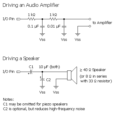
This figure shows how to connect an audio amplifier or speaker to hear these tones:

...and this figure shows how to connect the BASIC Stamp to the phone line:

The following DTMFOUT instruction will generate DTMF tones on I/O pin 0:
  ' Call Parallax
  DTMFOUT 0, [1, 9, 1, 6, 6, 2, 4, 8, 3, 3, 3]
If the BASIC Stamp is connected to the phone line properly, the above command would be equivalent to dialing 1-916-624-8333 from a phone keypad. If you wanted to slow the pace of the dialing to accommodate a noisy phone line or radio link, you could use the optional OnTime and OffTime values:
 ' Call Parallax; dial slowly.
  DTMFOUT 0, 500, 100, [1, 9, 1, 6, 6, 2, 4, 8, 3, 3, 3]
In this example, on a BS2 theOnTime is set to 500 ms (1/2 second) and OffTime to 100 ms (1/10th second).
| Tone Value | Corresponding Telephone Key |
| 0 - 9 | Digits 0 through 9 |
| 10 | Star (*) |
| 11 | Pound (#) |
| 12 - 15 | Fourth column tones A through D |
The BASIC Stamp microcontroller is a purely digital device. DTMF tones are analog waveforms, consisting of a mixture of two sine waves at different audio frequencies. So how does a digital device generate analog output? The BASIC Stamp creates and mixes the sine waves mathematically, then uses the resulting stream of numbers to control the duty cycle of a very fast pulse-width modulation (PWM) routine. So what's actually coming out of the I/O pin is a rapid stream of pulses. The purpose of the filtering arrangements shown in the figures above is to smooth out the high-frequency PWM, leaving only the lower frequency audio behind.
Keep this in mind if you want to interface a BASIC Stamp module's DTMF output to radios and other equipment that could be adversely affected by the presence of high-frequency noise on the input. Make sure to filter the DTMF output thoroughly. The circuits above are only a starting point; you may want to use an active low-pass filter with a roll-off point around 2 kHz.
BASIC Stamp Help Version 2.5.4
Copyright © Parallax Inc.
8/8/2012