![]()
![]()
![]()
Syntax: I2CIN Pin, SlaveID,{Address {\LowAddress},} [InputData]
Receive data from a device using the I2C® protocol.
| BS2p, BS2pe, and BS2px | ||
| Value of Pin | 0 | 8 |
| I/O Pin Arrangement | 0: Serial Data (SDA) pin 1: Serial Clock (SCL) pin |
8: Serial Data (SDA) pin 9: Serial Clock (SCL) pin |
| Transmission Rate | Approximately 81 kBits/sec (BS2p), 45 kBits/sec (BS2pe), 83 kBits/sec (BS2px) -- not including overhead. | |
| Special Notes | Both the SDA and SCL pins must have 4.7 kΩ
pull-up resisters. The I2CIN command does not allow for multiple masters. The BASIC Stamp cannot operate as an I2C slave device. |
|
| Related Commands | ||
The I2C protocol is a form of synchronous serial communication developed by Philips Semiconductor. It only requires two I/O pins and both pins can be shared between multiple I2C devices. The I2CINcommand allows the BASIC Stamp to receive data from an I2C device.
The following is an example of the I2CIN command:
result  VAR     Byte

Main:
  I2CIN 0, $A1, 0, [result]
  STOP
This code will transmit a "read" command to an I2C device (connected to I/O pins 0 and 1) and then will receive one byte and store it in the variable result. Though it may seem strange, the I2CIN command first transmits some data and then receives data. It must first transmit information (ID, read/write and address) in order to tell the I2C device what information it would like to receive. The exact information transmitted ($A1, 0) depends on the I2C device that is being used.
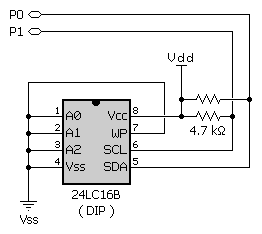
The example above will read a byte of data from location 0 of a 24LC16B EEPROM from Microchip. The figure below shows the proper wiring for this example to work. The SlaveID argument ($A1) is both the ID of the chip and the command to read from the chip; the 1 means read. The Address argument (0) is the EEPROM location to read from. Note that the I2CIN command will make up to eight attempts to connect to the addressed device. If the device does not properly respond, the I2CIN command will timeout and the InputData will remain unchanged.
Note: The 4.7 kΩ resisters are required for the I2CINcommand to function properly.

The I2CIN command's InputData argument is similar to the SERIN command's InputData argument. This means data can be received as ASCII character values, decimal, hexadecimal and binary translations and string data as in the examples below. (Assume the 24LC16B EEPROM is used and it has the string, "Value: 3A:101" stored, starting at location 0).
value   VAR     Byte(13)

Main:
  I2CIN 0, $A1, 0, [value]              ' receive ASCII code for "V"
  I2CIN 0, $A1, 0, [DEC value]          ' receive number 3
  I2CIN 0, $A1, 0, [HEX value]          ' receive number $3A
  I2CIN 0, $A1, 0, [BIN value]          ' receive number %101
  I2CIN 0, $A1, 0, [STR value\13]       ' receive string "Value: 3A:101"
  STOP
The tables below list all the available conversion formatters and special formatters available to the I2CIN command. See the SERIN command for additional information and examples of their use.
| Conversion Formatter | Type of Number | Numeric Characters Accepted | Notes |
| DEC{1..5} | Decimal, optionally limited to 1 - 5 digits | 0 through 9 | 1 |
| SDEC{1..5} | Signed decimal, optionally limited to 1 - 5 digits | -, 0 through 9 | 1,2 |
| HEX{1..4} | Hexadecimal, optionally limited to 1 - 4 digits | 0 through 9, A through F | 1,3 |
| SHEX{1..4} | Signed hexadecimal, optionally limited to 1 - 4 digits | -, 0 through 9, A through F | 1,2,3 |
| IHEX{1..4} | Indicated hexadecimal, optionally limited to 1 - 4 digits | $, 0 through 9, A through F | 1,3,4 |
| ISHEX{1..4} | Signed, indicated hexadecimal, optionally limited to 1 - 4 digits | -, $, 0 through 9, A through F | 1,2,3,4 |
| BIN{1..16} | Binary, optionally limited to 1 - 16 digits | 0, 1 | 1 |
| SBIN{1..16} | Signed binary, optionally limited to 1 - 16 digits | -, 0, 1 | 1,2 |
| IBIN{1..16} | Indicated binary, optionally limited to 1 - 16 digits | %, 0, 1 | 1,4 |
| ISBIN{1..16} | Signed, indicated binary, optionally limited to 1 - 16 digits | -, %, 0, 1 | 1,2,4 |
| NUM | Generic numeric input; hex or binary number must be indicated | $, %, 0 through 9, A through F | 1,3,4 |
| SNUM | Similar to NUM with value treated as signed with range -32768 to +32767 | -, $, %, 0 through 9, A through F | 1,2,3,4 |
| Special Formatter | Action |
| STR ByteArray \L {\E} | Input a character string of length L into an array. If specified, an end character E causes the string input to end before reaching length L. Remaining bytes are filled with 0s (zeros). |
| WAITSTR ByteArray {\L} | Wait for a sequence of bytes matching a string stored in an array variable, optionally limited to L characters. If the optional L argument is left off, the end of the array-string must be marked by a byte containing a zero (0). |
| SKIP Length | Ignore Length bytes of characters. |
| SPSTR Length | Buffer Length bytes (up to 126) of serial characters to Scratchpad RAM, starting at location 0. Use GET to retrieve the characters. |
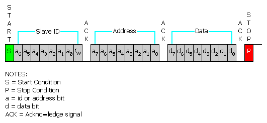
The I2C protocol has a well-defined standard for the information passed at the start of each transmission. First of all, any information sent must be transmitted in units of one byte (8-bits). The first byte, we call the SlaveID, is an 8-bit pattern whose upper 7-bits contain the unique ID of the device you wish to communicate with. The lowest bit indicates whether this is a write operation (0) or a read operation (1). Here is the SlaveID format:
| 7 | 6 | 5 | 4 | 3 | 2 | 1 | 0 |
| A6 | A5 | A4 | A3 | A2 | A1 | A0 | R/W |
The second byte, immediately following the SlaveID, is the Address. It indicates the 8-bit address (within the device) containing the data you would like to receive.
Some devices require more than eights bits of address. For this case, the optional LowAddress argument can be used for the low-byte of the required address. When using the LowAddress argument, the Address argument is effectively the high-byte of the address value. For example, if the entire address value is 2050, use 8 for the Address argument and 2 for the LowAddress argument (8 * 256 + 2 = 2050).
Following the last address byte is the first byte of data. This data byte may be transmitted or received by the BASIC Stamp. In the case of the I2CINcommand, this data byte is transmitted by the device and received by the BASIC Stamp. Additionally, multiple data bytes can follow the address, depending on the I2C device. Note that every device has different limitations regarding how may contiguous bytes they can receive or transmit in one session. Be aware of these device limitations and program accordingly.
Every I2C transmission session begins with a Start Condition and ends with a Stop Condition. Additionally, immediately after every byte is transmitted, an extra clock cycle is used to send or receive an acknowledgment signal (ACK). All of these operations are automatically taken care of by the I2CIN command so that you need not be concerned with them. The general I2C transmission format is shown below.

Since the I2CIN command is intended for input only, it actually overrides the "R/W" bit (bit 0) in the SlaveID argument. This is done so that it can use the I2C protocol's "Combined Format" for receiving data. Put simply, this means a command such as:
I2CIN 0, $A1, 10, [result]
...actually transmits $A0, then 10, then $A1 and then it reads the data back from the device. The $A0 means "write", the 10 is the address to write to and, finally, the $A1 indicates a change of direction; to "read" the location, instead. Even though the I2CIN command really doesn't care what the value of the SlaveID's LSB is, it is suggested that you still set it appropriately for clarity.
Also note that the I2CIN command does not support multiple I2C masters and the BASIC Stamp cannot operate as an I2C slave device.
BASIC Stamp Help Version 2.5.4
Copyright © Parallax Inc.
8/8/2012