![]()
![]()
![]()
Syntax: OWOUT Pin, Mode, [OutputData]
Send data to a device using the Maxim/Dallas Semiconductor 1-Wire®protocol.
| BS2p, BS2pe, and BS2px | |
| Transmission Rate | Approximately 20 kbits/sec (low speed, not including reset pulse) |
| Special Notes | The DQ pin (specified by Pin) must have a 4.7 kΩ pull-up resister. |
| Related Commands |
The 1-Wire protocol is a form of asynchronous serial communication developed by Maxim/Dallas Semiconductor. It only requires one I/O pin and that pin can be shared between multiple 1-Wire devices. The OWOUT command allows the BASIC Stamp to send data to a 1-Wire device.
The following is an example of the OWOUT command:
OWOUT 0, 1, [$4E]
This code will transmit a "reset" pulse to a 1-Wire device (connected to I/O pin 0) and then will detect the device's "presence" pulse and then transmit one byte (the value $4E).
The Mode argument is used to control placement of reset pulses (and detection of presence pulses) and to designate byte vs. bit input and normal vs. high speed†. The tables below show the meaning of each of the four bits of Mode and some of the 16 possible values and their effect.
| Bit | Function |
| 0 | Front-End Reset • 0 = No reset • 1 = Generate reset before data |
| 1 | Back-End Reset • 0 = No reset • 1 = Generate reset after data |
| 2 | Bit / Byte Transfer • 0 = Byte • 1 = Bit |
| 3 | Low / High Speed† • 0 = Low • 1 = High |
| Mode | Effect |
| 0 | No Reset, Byte mode, Low speed |
| 1 | Reset before data, Byte mode, Low speed |
| 2 | Reset after data, Byte mode, Low speed |
| 3 | Reset before and after data, Byte mode, Low speed |
| 4 | No Reset, Bit mode, Low speed |
| 5 | Reset before data, Bit mode, Low speed |
| 6 | Reset after data, Bit mode, Low speed |
| 7 | Reset before and after data, Bit mode, Low speed |
| 8 | No Reset, Byte mode, High speed† |
| 9 | Reset before data, Byte mode, High speed† |
† The BS2pe is not capable of High Speed transfers.
The proper value for Mode depends on the 1-Wire device and the portion of the communication you're working on. Please consult the data sheet for the device in question to determine the correct value for Mode. In many cases, however, when using the OWOUT command, Mode should be set for a Front-End Reset (to initialize the transaction). This may vary due to device and application requirements, however.
When using the Bit (rather than Byte) mode of data transfer, all variables in the OutputData argument will only transmit one bit. For example, the following code could be used to send two bits using this mode:
bitOne  VAR     Bit
bitTwo  VAR     Bit

Init:
  bitOne = 0
  bitTwo = 1

Main:
  OWOUT 0, 5, [bitOne, bitTwo]
  STOP
In the code above, we chose the value "5" for Mode. This sets Bit transfer and Front-End Reset modes. Also, we could have chosen to make the bitOne and bitTwo variables each a byte in size, but the BASIC Stamp would still only use the their lowest bit (Bit0) as the value to transmit in the OWOUT command (due to the Mode we chose).
The OWOUT command's OutputData argument is similar to the DEBUG and SEROUT command's OutputData argument. This means data can be sent as literal text, ASCII character values, repetitive values, decimal, hexadecimal and binary translations and string data as in the examples below.
value   VAR     Byte

Init:
  value = 65

Main:
  OWOUT 0, 1, [value]                                   ' send ASCII character "A"
  OWOUT 0, 1, [REP value\5]                             ' send "A" 5x, ie: "AAAAA"
  OWOUT 0, 1, [DEC value]                               ' send "6" and "5"
  OWOUT 0, 1, [HEX value]                               ' send "4" and "1"
  OWOUT 0, 1, [BIN value]                               ' send "1000001"
  STOP
The tables below list all the available special formatters and conversion formatters available to the OWOUT command. See the DEBUG and SEROUT commands for additional information and examples of their use.
| Special Formatter | Action |
| ? | Displays "symbol = x' + carriage return; where x is a number. Default format is decimal, but may be combined with conversion formatters (ex: BIN ? x to display "x = binary_number"). |
| ASC ? | Displays "symbol = 'x'" + carriage return; where x is an ASCII character. |
| STR ByteArray {\L} | Send character string from an array. The optional \L argument can be used to limit the output to L characters, otherwise, characters will be sent up to the first byte equal to 0 r the end of RAM space is reached. |
| REP Byte\L | Send a string consisting of Byte repeated L times (ex: REP "X"\10 sends "XXXXXXXXXX"). |
| Conversion Formatter | Type of Number | Notes |
| DEC{1..5} | Decimal, optionally fixed to 1 - 5 digits | 1 |
| SDEC{1..5} | Signed decimal, optionally fixed to 1 - 5 digits | 1,2 |
| HEX{1..4} | Hexadecimal, optionally fixed to 1 - 4 digits | 1 |
| SHEX{1..4} | Signed hexadecimal, optionally fixed to 1 - 4 digits | 1,2 |
| IHEX{1..4} | Indicated hexadecimal, optionally fixed to 1 - 4 digits | 1 |
| ISHEX{1..4} | Signed, indicated hexadecimal, optionally fixed to 1 - 4 digits ($ prefix) | 1,2 |
| BIN{1..16} | Binary, optionally fixed to 1 - 16 digits | 1 |
| SBIN{1..16} | Signed binary, optionally fixed to 1 - 16 digits | 1,2 |
| IBIN{1..16} | Indicated binary, optionally fixed to 1 - 16 digits | 1 |
| ISBIN{1..16} | Signed, indicated binary, optionally fixed to 1 - 16 digits | 1,2 |
The 1-Wire protocol has a well-defined standard for transaction sequences. Every transaction sequence consists of four parts: 1) Initialization, 2) ROM Function Command, 3) Memory Function Command, and 4) Transaction/Data. Additionally, the ROM Function Command and Memory Function Command are always 8 bits wide (1 byte in size) and is sent least-significant-bit (LSB) first.
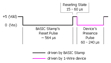
The Initialization part consists of a reset pulse (generated by the master) and will be followed by a presence pulse (generated by all slave devices). The figure below details the reset pulse generated by the BASIC Stamp and a typical presence pulse generated by a 1-Wire slave, in response.

This reset pulse is controlled by the lowest two bits of the Mode argument in the OWIN command. It can be made to appear before the ROM Function Command (ex: Mode = 1), after the Transaction/Data portion (ex: Mode = 2), before and after the entire transaction (ex: Mode = 3) or not at all (ex: Mode = 0). See the section on Mode, above, for more information.
Following the Initialization part is the ROM Function Command. The ROM Function Command is used to address the desired 1-Wire device. The table below shows common ROM Function Commands. If only a single 1-Wire device is connected, the Match ROM command can be used to address it. If more than one 1-Wire device is attached, the BASIC Stamp will ultimately have to address them individually using the Match ROM command.
| Command | Value (HEX) | Action |
| Read ROM | $33 | Reads the 64-bit ID of the 1-Wire device. This command can only be used if there is a single 1-Wire device on the line. |
| Match ROM | $55 | This command, followed by a 64-bit ID, allows the BASIC Stamp to address a specific 1-Wire device. |
| Skip ROM | $CC | Address a 1-Wire device without its 64-bit ID. This command can only be used if there is a single 1-Wire device on the line. |
| Search ROM | $F0 | Reads the 64-bit IDs of all the 1-Wire devices on the line. A process of elimination is used to distinguish each unique device. |
The third part, the Memory Function Command, allows the BASIC Stamp to address specific memory locations, or features, of the 1-Wire device. Refer to the 1-Wire device's data sheet for a list of the available Memory Function Commands.
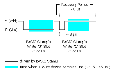
Finally, the Transaction/Data section is used to read or write data to the 1-Wire device. The OWOUT command will write data at this point in the transaction. A write is accomplished by generating a low-pulse of a varying width to indicate a 0 or a 1. This is called a "Write Slot" and must be at least 60 us wide. The figure below shows typical Write Slots performed by the BASIC Stamp. See the OWIN command for information on Read Slots.

BASIC Stamp Help Version 2.5.4
Copyright © Parallax Inc.
8/8/2012