![]()
![]()
![]()
![]()
![]()
![]()
![]() {PBASIC 2.5}
{PBASIC 2.5}
Example
![]()
![]()
![]()
![]()
![]()
![]()
![]() {PBASIC 2.5}
{PBASIC 2.5}
Example
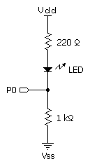
Connect an LED and two resistors as shown below for the demo program.

' REVERSE.BS1
' Connect the circuit shown in the REVERSE command description to I/O pin
' 0 and run this program.  The LED will alternate between two states, dim
' and bright. The BASIC Stamp is using the REVERSE command to toggling I/O
' pin 0 between input and output states. When pin 0 is an input, current
' flows through R1, through the LED, through R2 to ground. Pin 0 is
' effectively disconnected and doesn't play a part in the circuit. The total
' resistance encountered by current flowing through the LED is R1 + R2 = 1220
' ohms. When pin 0 is reversed to an output, current flows through R1, through
' the LED, and into pin 0 to ground (because of the 0 written to PIN0). The
' total resistance encountered by current flowing through the LED is R1,
' 220 ohms. With only 20% of the resistance, the LED glows brighter.

' {$STAMP BS1}
' {$PBASIC 1.0}


Setup:
  PIN0 = 0                              ' Put a low in the pin 0
                                        '  output driver
Main:
  PAUSE 250                             ' 1/4th second pause
  REVERSE 0                             ' reverse pin 0 I/O direction
  GOTO Main                             ' do forever
NOTE: The example below is written for the BS2 and will run on any of the BS2-family modules. Modify the $STAMP directive (as required) before downloading to the BS2e, BS2sx, BS2p, BS2pe, or BS2px.
 REVERSE.BS2
' Connect the circuit shown in the REVERSE command description to I/O pin
' 0 and run this program.  The LED will alternate between two states, dim
' and bright. The BASIC Stamp is using the REVERSE command to toggling I/O
' pin 0 between input and output states. When pin 0 is an input, current
' flows through R1, through the LED, through R2 to ground. Pin 0 is
' effectively disconnected and doesn't play a part in the circuit. The total
' resistance encountered by current flowing through the LED is R1 + R2 = 1220
' ohms. When pin 0 is reversed to an output, current flows through R1, through
' the LED, and into pin 0 to ground (because of the 0 written to OUT0). The
' total resistance encountered by current flowing through the LED is R1,
' 220 ohms. With only 20% of the resistance, the LED glows brighter.

' {$STAMP BS2}
' {$PBASIC 2.5}


Setup:
  OUT0 = 0                              ' Put a low in the pin 0
                                        '  output driver
Main:
  PAUSE 250                             ' 1/4th second pause
  REVERSE 0                             ' reverse pin 0 I/O direction
  GOTO Main                             ' do forever
BASIC Stamp Help Version 2.5.4
Copyright © Parallax Inc.
8/8/2012